
PATRIOT: The Cornerstone of Western Air & Missile Defense
By Zach Abid.
On February 24, 2022, Russia unleashed Europe’s largest and deadliest war since the Second World War. It brought to bear its arsenal of ballistic and cruise missiles against targets in Ukraine, ranging from air bases to power plants and other civilian infrastructure. Due to the worsening air defense situation and Ukraine’s limited inventory of SA-10s, the United States announced that it was transferring a Patriot battery to Ukraine in December 2022. In close consultation with the United States, Germany and the Netherlands followed suit and announced in January 2023 that they were also sending a Patriot battery to Ukraine.
The Patriot battery from the United States arrived in Kyiv in early May 2023 and scored its first kill against Russia’s AS-24 Killjoy air-launched ballistic missile (ALBM) during a large missile raid.
MIM-104 Patriot is the mainstay Air and Missile Defense system of the United States (US) Army. The system, which entered service in the mid-80s, was made to replace the Army’s MIM-23 Home All The Way Killer (HAWK) and Nike Hercules weapon systems.
The role of the Patriot is to defend ground forces against enemy aircraft, cruise missiles, and some ballistic missiles. Although it is primarily oriented toward protecting against Air Breathing Threats (ABTs), its coverage against tactical ballistic missiles (TBMs) complements the Army’s Terminal High Altitude Area Defense (THAAD) system, which provides the so-called “upper tier” defense against ballistic missiles (BMs) with longer ranges.
The smallest formation of a Patriot system is the fire unit (FU), in US service, Patriot is organized into batteries, with one FU corresponding to one battery. To work effectively, these batteries are deployed in battalions, which are the basic Air Defense Artillery (ADA) unit. A typical pure Patriot Battalion will consist of a Headquarters and Headquarters Battery; four firing batteries lettered Alpha, Bravo, Charlie, and Delta; and an Echo Maintenance Company. Multiple battalions can be grouped to form brigades.
In Dutch and German service, Patriot is organized into squadrons, with one squadron being equivalent to a US battery. These squadrons are then combined to form groups, which are equivalent to US battalions. Multiple groups form a Wing, which can be seen as being equivalent of a US brigade.
Since it entered service, there have been significant changes to the organization of Patriot batteries, and the overall structure remains malleable to this day. But for simplicity’s sake, a typical battery today consists of a battery headquarters, a fire control platoon, a launcher platoon, and a maintenance platoon.
Equipment

Figure 1.
There are five major pieces of equipment associated with the Patriot at the battery level: the Battery Command Post (BCP), Engagement Control Station (ECS), Radar Set (RS), Launcher Station (LS), Antenna Mast Group (AMG), and Electric Power Plant (EPP) (Fig. 1).
The Radar Set (RS) can include either the AN/MPQ-53 radar or the AN/MPQ-65 radar. Nowadays most, if not all, US batteries have moved to the AN/MPQ-65 radar, which is an upgrade of the AN/MPQ-53. This is a multifunctional radar that serves as the eyes of the battery. This single radar is responsible for detecting and track-ing incoming ABTs and TBMs, as well as guiding the Patriot missiles toward their targets. The RS has a claimed range of about 180 to 200 kilometers and a field of view of 120-degrees when searching.
The Launcher Station is, as the name implies, a launcher that holds Patriot missiles. There are three launcher variants: the M901, which can carry the PAC-1 and 2 missiles; the M902, which can carry the PAC-1, 2, and PAC-3 CRI missiles; and the M903, which can carry all the previously missiles, and the newer PAC-3 MSE. The M902 and M903 are reconfigurable, meaning they can be loaded to have a combo of different missiles on the same launcher.
The Antenna Mast Group (AMG) OE-349 is used by the battery for inter-battalion communications with other batteries and battalion assets. The Electric Power Plant (EPP) AN/MJQ-24 provides power for the RS, the ECS, and the AMG. This power is provided by two 150-kilowatt generators mount-ed on an M977 Heavy Expanded Mobility Tactical Truck (HEMTT) chassis. The LS has its own independent source of power in the form of a 15-kilowatt generator.
The Engagement Control Station (ECS) AN/MSQ-132 is the brain of the battery. It connects with all the pieces of equipment in the battery. Inside the ECS are two operator consoles and the Enhanced Weapons Control Computer (EWCC). From here, the operators can select to operate the EWCC in either semiautomatic or automatic mode. In semiautomatic mode, the EWCC processes what the RS detects, determines whether the radar tracks show a friend or foe, the operators then manually select targets for engagement. In automatic mode, the EWCC detects, processes, and if it determines a target to be a threat, engages it. In this mode, operators can override engagements.
The Battery Command Post (BCP) serves as the working space for the battery commander and his staff. The command post vehicle is also equipped with an Air and Missile Defense Workstation (AMDWS) that allows the commander to plan air and missile defense battles. The BCP vehicle also has communications equipment that allows it to receive and transmit TADIL-J (Link 16) data from external sources such as the Airborne Early-Warning and Control (AEWC) Aircraft.
Deployment

Figure 2.
The deployment of a Patriot battery starts with the selection of battery crew members to be part of a reconnaissance, selection, and occupation of position (RSOP) team. The job of the RSOP team is to find the best terrain and equipment sites that enable the Patriot battery to perform its mission.
This involves finding and determining primary and secondary positions of emplacement, primary and alternate access routes, the trafficability of roads and bridges, major terrain features, and possible ambush areas.
Once the RSOP team finds a suitable position, the first piece of equipment to be emplaced is the RS. Due to the RS’ field of view limitations, the primary and secondary target lines (P/STLs) assigned to the battery must be taken into consideration. A PTL is a sector of fire where a battery is assigned in which the battery will engage threats as they appear in this sector. The STL are sectors in the adjoining areas on both sides of the PTL.
All other pieces of equipment are placed in relation to the RS. The EPP and ECS are emplaced to the rear of the RS as well as the AMG. The LS are normally placed in three different positions to counter different threats. These are local launchers, remote launchers Phase 1 (RL-1), or else remote launchers Phase 3 (RL-3) (Fig. 2).

Figure 3, 4.
When a battery is using local LS positioning, the LS are in front of the RS at a minimum distance of 130 meters and a maximum distance of 1,200 meters. Local LS are best suited for countering ballistic missiles and aerial threats. LS can be seated in what is known as a “Lazy W” formation (Fig. 3). With RL-1 positioning, the LS are still located forward of the RS, but they can be placed 10 kilometers away. LS for RL-1 is emplaced evenly on both sides of the PTL.
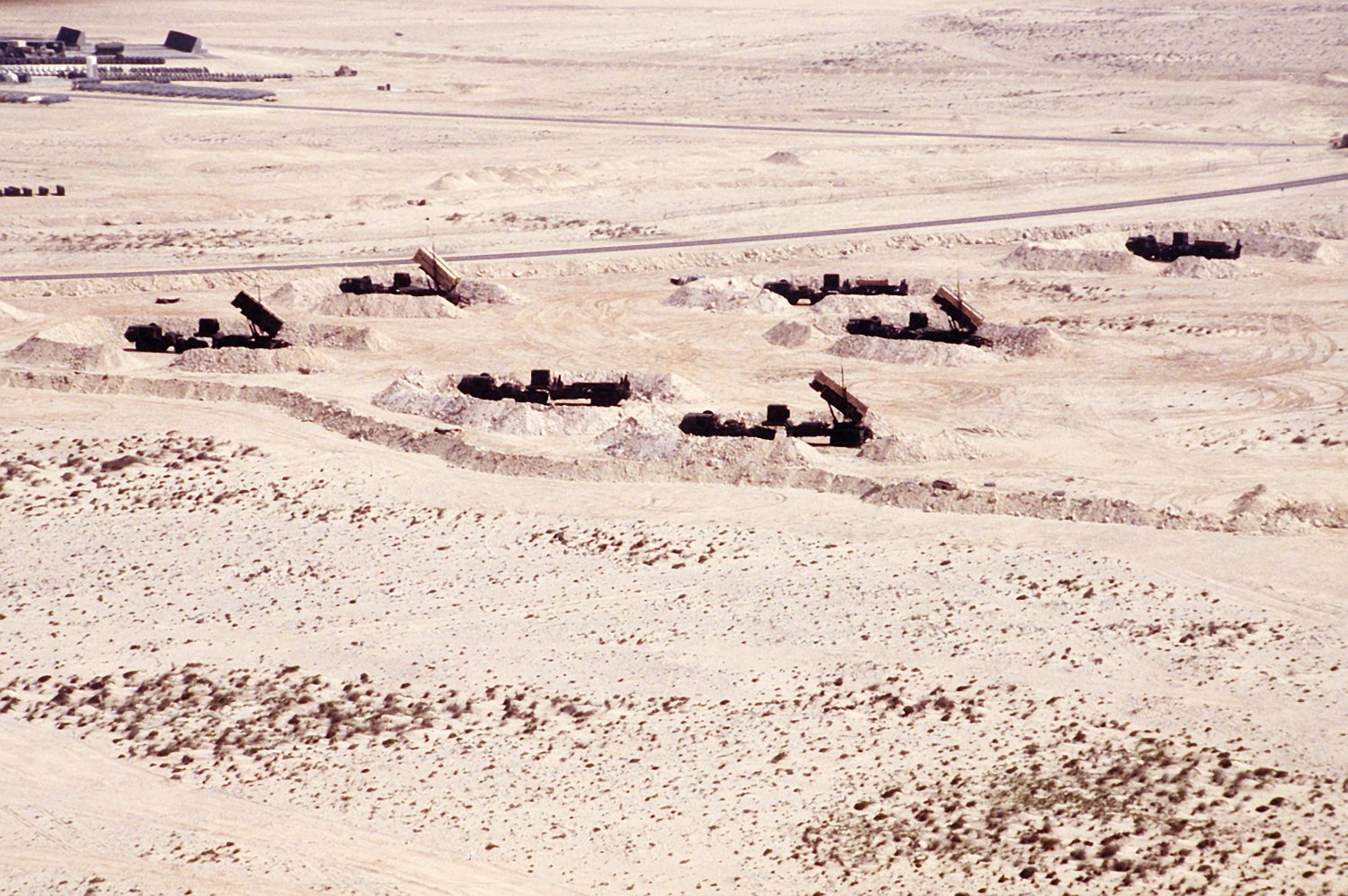
RL-3 allows for LS to be emplaced 30 kilometers away from the RS. This emplacement is best suited for TBM defense. With RL-3 emplacement, LS are grouped in what is known as a “launcher farm”. This launcher farm needs an AN/MRC-137 Communications Relay Group (CRG) vehicle alongside an AMG. The CRG vehicle acts as a Launcher Control Station (LCS), while the AMG passes on launch information from the battery ECS to the CRG.
Other LS orientations might be used by batteries to counter certain threats. One of these formations includes the “Flying V” orientation, which was considered following the Aramco attack in 2019. Patriot units in Japan have also been experimenting with “weighted” LS emplacements that allow for better coverage against multiple threats by placing LS in STLs (Fig. 4).
Employment

Figure 5.
Patriot can be employed in both offensive and defensive ways when it is used in support of ground operations. Regardless of what kind of operations the system is conducting, Patriot is most effective when batteries fight as a battalion. When employed in the offensive, Patriot battalions assigned to a corps will provide coverage to the corps’ maneuver units that form the main effort and to their support facilities, C3, logistics operations, and reserve forces.
Due to its design, Patriot cannot move with other corps units when they are conducting an attack. Nonetheless, Patriot still has to provide coverage for these units, as this is when they are most vulnerable to attack.
To do this, Patriot batteries can be placed near the line of departure (LD), where they can provide forward coverage for the maneuver units. Once these units have crossed the LD, batteries in the rear can move forward behind the advancing force to emplace at pre-planned locations. Because Patriot can’t fire on the move, the system is vulnerable to attack while moving to these new positions.
As such, the initial batteries at the LD provide protection for these forward batteries in a method known as “bounding overwatch” or “leapfrogging.” Once the forward batteries have emplaced and become operational, the batteries at the LD move to forward positions, and so on, to the conclusion of the operation (Fig. 5).
Patriot batteries can also be used in defensive operations. During defensive operations, the batteries are deployed in the rear to protect the corps’ rear area assets, or else they might be employed by echelons above corps (EACs) to provide protection for critical fixed assets.
During defensive operations, the batteries can be deployed in multiple orientations, depending on the threat the battalion faces, and the resources available to the battalion. These orientations are convergent PTLs, divergent PTLs, and parallel PTLs (Fig. 6-8). Against ABT and TBM threats, the fire units are best positioned in an orientation that allows for converging PTLs. This tactic allows for mutual support of fires, defense in depth, and effective overlap of fires, but at the cost of additional coverage. Parallel and divergent PTL orientations can be used when the battalion needs to cover more area, there are too few batteries for a convergent PTL orientation, or there are multiple avenues of attack.

Figure 6, 7, 8.
Getting Ballistic Missile Defense
The Patriot system, as originally fielded in the early 1980s, was not optimized for intercepting TBMs. However, the original requirements for the SAM-D (Surface-to-Air Missile, Development) program, which later became Patriot, included capabilities to defend against TBMs.
This requirement was removed at later stages for two reasons. The first reason was driven by the Training and Doctrine Command (TRADOC), which argued against it due to the perceived cost, schedule, and technical difficulties that would come from pursuing ABT and TBM defense capabilities simultaneously. The second reason was driven by the belief that long-range Free Rockets Over Ground (FROG), which Patriot was intended to self-protect against, lacked the accuracy to target Patriot batteries at range.
Nonetheless, in 1979, a Patriot missile intercepted a Nike Hercules missile in a test that took place at the White Sands Missile Range. This was the first anti-missile flight test conducted by the Patriot and show-cased the Patriot’s inherent TBM defense capabilities.
In the late 1970s and early 1980s, the Soviets started deploying advanced ballistic missiles with better accuracy in the form of SS-21 Scarab and SS-23 Spider. This led to a re-evaluation of Patriot’s ballistic missile defense role.
A conference was held in the spring of 1983 with the aim of working out how Patriot could deal with this problem. This conference was chaired by Brig. Gen. Max Bunyard, then Patriot Project Manager (PM), and his replacement, Brig. Gen. Donald Infante. The outcome of this conference were the Patriot Anti-Tactical Missile Capability 1 and 2 programs. In early 1985, Colonel Lawrence Capps, who then succeeded Infante, secured funding for the PAC-1 and 2 programs. In December of that same year, the Office of the Secretary of Defense approved a multiyear procurement contract worth $3.5 billion for the Patriot program. This provided a more stable funding cushion for the PAC-1 and 2 programs.
By July 1986, the software changes implemented as part of the Patriot Advanced Capability (PAC) 1 phase were complete. These changes involved software updates to the RS, giving it a high-altitude search mode for tracking incoming ballistic missiles, and software changes to the missile that gave it better trajectory shaping.
For the time being, this only gave the Patriot a limited self-defense capability against simple TBMs and rockets, such as the SS-21 Scarab and FROG, by knocking them off their intended course. The PAC-1 still lacked the capability to disable the warheads on the threat systems. The success of these changes was validated on the 11th of September that same year in a test that took place at White Sands. A modified Patriot missile intercepted a Lance ballistic missile simulating an SS-21 at an altitude of 7.9 kilometers (26k feet) and 13 kilometers (8 miles) away from the LS.
Production cut-in for the PAC-1 missile soon followed in December of that year. This brought a close to the first phase of the Patriot Anti-Tactical Missile Capability program. In total, $32 million was spent on capability development for PAC-1. The second phase of the program, PAC-2, was already underway in 1986, with Raytheon, the main contractor, receiving a $51 million contract in August of 1986 for the development of the PAC-2.
Some of the major changes under the PAC-2 program involved physical alterations to the Patriot missiles warhead, fuse, and guidance software. The Army wanted the PAC-2 missile to disable or significantly damage the explosive warheads on incoming TBMs. This is due to the PAC-1s inability to fully disable warheads on TBMs, which would have resulted in warheads still exploding after either impacting the ground or else littering a defended area with large amounts of unexploded ordinance (UXO).
The new warhead was not to substantially exceed the size and weight of the existing warhead. As such, designers set about trying to achieve this challenging task by changing the spray pattern, size, and velocity of the warhead fragments. A new dual-use fuse, capable of handling higher closing speeds against longer-range TBMs, was also introduced. The guidance segment enhancements were software-based and allowed for better trajectory shaping against new threats.
The development of PAC-2 lasted from 1986 to 1988. During this period, the program office conducted a range of tests, from component-level to system-level hardware and software tests. The test pro-gram was successful and paved the way for PAC-2 production cut-in, which was approved in December 1988, with actual production cut-in starting in February of the following year.
The initial delivery of the first PAC-2 missiles took place in August of 1989; however, these were a handful of missiles meant to be used for operational testing. The first unit equipped with PAC-2 missiles would take place in January of 1990, six months after the release of its accompanying Post Deployment Build-3 (PDB-3) software. However, Saddam Hussein and the universe had other plans for this schedule. On August 2, 1990, Saddam Hussein’s forces invaded Kuwait.
The Patriot Program Office was forced to release the PDB-3 software build early and start production acceleration for the PAC-2 missiles. Raytheon and other subcontractors began working 24-hour shifts at their respective factories.
As the conflict in Kuwait unfolded into a larger war involving the US, Patriot operators that were deployed to protect allied forces were faced with the task of defending coalition forces against modified Iraqi Scud variants.
Here, Patriot’s capabilities were stretched to their limits. As we discussed earlier, the PAC-2 missiles being delivered in 1990 were only capable of intercepting short-range TBMs. But in 1991, operators were forced to use the missile for intercepting longer-range missiles, many of which were re-entering erratically due to custom modifications done by the Iraqis to extend the range of the missiles. The disintegration of the Scud missiles also proved to be a difficult problem for the RS to handle. These disintegrating pieces led the RS to detect more targets, which resulted in several of these being classified as TBMs by the WCC. Patriot operators were forced to engage these targets which led to higher-than-expected missile expenditures. Software upgrades were implemented to address the discrimination issues.
However, it became evident that, much like the PAC-2 missile, the AN/MPQ-53 radar was not optimized for dealing with the complex phenomenology that came with these particular TBMs. Taking into account the issues encountered in 1991, the Army initiated the Quick Reaction Program (QRP). The aim of the QRP was immediately improving Patriot’s performance before moving onto a more extensive upgrade program.
The first major upgrade under the QRP involved a low-noise receiver upgrade to the AN/MPQ-53; this lowered the noise figure by approximately 6.5 decibels (dB). The beam-steering processor for the RS was also upgraded, which reduced the sidelobes by approximately 5 dB. A new radar shroud was added to eliminate backlobe and interference from other radars. Other improvements centered around ease of emplacement were also implemented, including the introduction of a North Finding System and the ability to utilize the Global Positioning System (GPS). The LSs were modified to allow for RL-1 emplacement, which allowed for LS to be emplaced 12 km away from the RS.
The RS upgrades resulted in increased sensitivity, improved detection, and improved classification of targets in cluttered environments. The ease of emplacement and remote launcher upgrades increased the defended footprint of the Patriot and reduced the time needed to set up the battery. These near-term modifications took place between 1992 and 1993. The follow-on to the QRP was the third Patriot Advanced Capability (PAC-3) program. This was a three-phase program that would start with slowly rolling out upgrades to the major hardware of the Patriot and end with the introduction of a new missile.
The first phase, which is also known as Configuration 1, involved new modifications for the PAC-2 missile under the Guidance Enhancement Missile (GEM) effort. This involved replacing the existing E/F-band fuse with an S-band fuse. This new fuse provided a quicker reaction time than the previous one; it also increased the sensitivity and detection range, allowing the missile to handle even higher closing velocities with longer-range TBMs.
Moreover, three low noise amplifiers were added to the front end of the receiver. The monopulse seeker antenna was modified to support these changes. This receiver upgrade improved the sensitivity of the PAC-2’s seeker, allowing to better detect targets with low Radar Cross Section (RCS) such as the warheads of TBMs after separation. To increase the missile’s range, the case was switched to a lightweight composite material and the rocket motor enhanced with the addition of a more advanced propellant. Lastly, the programmable read-only memory onboard was modified to support an increased TVM data rate.
The RS’ Pulse Doppler Processor was upgraded to improve the pulse doppler waveform and reduce dwell times. While the ECS’ WCC was upgraded to an updated version known as the Enhanced Weapons Control Computer (EWCC), this improved the through-put of the system by a factor of four. The ECS also received an Optical Disk (OD) for loading new software, and a new data recorder was embedded to record usage data. These modifications began fielding in 1995, and by early 1997, all US battalions were upgraded to Configuration 1 standard.
Configuration 2 involved upgrades to the Information Coordination Center (ICC), enabling it to receive TADIL-J/A (Link 16) signals from external sources in the form of the Multifunctional Information Distribution System-Low Volume Terminal 2 (MIDS-LVT 2) terminals. The ICC sits at the battalion level and serves as the Fire Direction Center (FDC) of the bat-talion. It also facilitates external communications for batteries. This configuration also introduced the PDB-4 software build, which unlocked the full capabilities of the previous Pulse Doppler Processor upgrade. Configuration 2 modifications were completed in 1998. Together, these modifications increased the area defended by a Patriot battery by a factor of eight over the area its Gulf War counterpart defended in 1991.
The last phase under Configuration 3 introduced the most substantial changes. An additional traveling wave tube transmitter was introduced, allowing for a doubling of the duty cycle of the RS. This substantially increased the detection range of the RS and allowed the RS to be more multifunctional.
To improve the RS’ subclutter performance and discrimination capabilities, a new low-noise exciter was added. Wide-band capabilities were introduced for both transmit and receive. These changes together improved the RS’ range resolution and discrimination capabilities, allowing Patriot to better classify debris from targets of interest. Once the radar had received these modifications, it was designated the AN/MPQ-65. Further modifications were done on the ECS, ICC, and CRG to allow for even farther separation between LS and these elements as part of the RL-3.
To close off Configuration 3, a new missile with im-proved TBM capabilities was sought. Raytheon offered a modified version of the PAC-2 with an active Ka-band seeker that also featured a 0.76-meter rocket motor extension. Lockheed Martin Vought offered a missile employing novel Hit-to-Kill (HTK) technology paired with an active Ka-band seeker as well. The HTK technology used for this missile was something the Army and Vought had previously been experimenting with under the Flexible Lightweight Agile Guided Experiment (FLAGE) and later Extended Range Intercept (ERINT) programs.
HTK is essentially a technique that ensures the destruction of a ballistic missile by having the defending missile collide with it. The kinetic energy from this collision ensures the destruction of both missiles.
During the performance demonstrations of these two missiles, Raytheon’s missile performed well against ABTs and low-RCS targets. However, the missile struggled in tests that involved longer-range TBMs, especially those equipped with submunitions.
On the other hand, the Lockheed Martin Vought missile performed extremely well against TBMs equipped with submunitions and other maneuvering TBMs. But just like Raytheon’s bid, the Lockheed missile struggled with long-range intercepts against ABTs. This is owed to the missile’s smaller size and design characteristics that were more optimized for countering TBMs. The missile eventually selected for the PAC-3 program would be Lockheed’s missile based on the ERINT.
Following the introduction of the new PAC-3 missile, the LS’ Launcher Electronics Module (LEM), which handles messages between the LS and the ECS, was replaced with the Enhanced Launcher Electronic System (ELES). This new launcher was designated the M902. Furthermore, a new computer called the Fire Solution Computer (FSC) was introduced. The FSC is an adjacent computer that acts as a peripheral to the EWCC. This new computer was mainly responsible for handling all the processing requirements of the PAC-3.
The Missiles of Patriot
There are three major missiles used with the Patriot system today, these are the PAC-2 Guidance Enhancement Missile (GEM), PAC-3 Cost Reduction Initiative (CRI), and PAC-3 Missile Segment Enhancement (MSE).
PAC-2, GEM, GEM

The PAC-2 is the mainstay medium-to-long-range missile of the Patriot. It is designed to deal with ABTs such as enemy fighter aircraft, cruise missiles, enemy airborne early warning aircraft, and drones as small as an RQ-7 Shadow. The missile is 5.2 meters in length, 0.41 meters in diameter, has a wingspan of 0.92 meters and weighs 915 kg. At the front of the missile sits the radome, which is made from fused silica ceramic, and houses a 30.5-centimeter diameter steerable monopulse antenna. Behind it sits the terminal guidance hardware, which consists of a receiver, transmitter, and antenna control hardware.
Next is the Guidance Section, which houses the autopilot computer for the missile. The onboard computer generates steering commands based on seeker and uplink information from the RS. The missile’s 84-kg single-layer fragmentation warhead sits aft of the guidance section in the Warhead Section. The PAC-2s warhead was reduced by 7 kg com-pared to the PAC-1s, however, the preformed fragment size for this new warhead was increased from 1.9 grams of the PAC-1 to 45 grams. This section also contains four flush-mounted antennas for mid-course guidance, inertial sensors, and lastly, four E/F-band strip line fuse and arming devices.
This is followed by Thiokol’s 592 kg TX-486 solid-rocket motor in the Propulsion Section. The rocket motor measures 3.3 meters in length and 0.40 meters in diameter, produces 10,909 kg of thrust, and burns in 11.5 seconds. It uses a moderately-aluminized Hydroxyl-Terminated Polybutadiene (HTPB) propellant, which was introduced as an upgrade over the Carboxy-Terminated Polybutadiene (CTPB) used in the rocket motor previously. This made Patriot the first tactical missile using a HTPB propellant to enter production in the US.
Lastly, the Control Actuator Section (CAS), where the missile’s fins are mounted, is aft of the Propulsion Section. Inside this section are the fin servo systems, which are hydraulicly actuated and powered by an electrohydraulic power supply. The fin servo system turns the fins based on steering commands received from the missile’s autopilot computer. Two further flush-mounted guidance antennas are also located in this section.
The PAC-2 uses Track-via-Missile (TVM) guidance, meaning that after launch, the RS illuminates the target for the missile. The missile’s seeker acquires the return signal from the target and passes on that signal to the RS.
The computer on the ECS then calculates and compares the difference between the missile’s return signal and what the RS observes. New information on the target is then sent back to the missile. This process continues back and forth, the error is reduced, and the missile flies closer and closer to the target until an interception occurs.
The missile has a public range of about 160 kilometers (90 miles) against ABT threats and employs a conventional blast-fragmentation warhead. While not its primary role, PAC-2 can also intercept short-range TBMs. When defending against TBMs, the missile has a demonstrated range of about 13 to 15 kilometers (8 to 9 miles).
PAC-3, CRI

The PAC-3 is a short-to-medium-range missile of the Patriot. The missile is mainly meant to intercept TBMs but retains some capabilities against ABTs.
The PAC-3 missile is 5.1 meters in length, 0.26 meters in diameter, and weighs 315 kg. At the front of the missile sits an active Ka-band monopulse seeker antenna housed in a ceramic radome. The radome also houses the two-axis gimbal platform the antenna is mounted on and the associated electronics. To the aft of this sit the Master Frequency Generator (MFG), Transmitter, Microwave Receiver Unit (MRU), Intermediate Frequency Processor (IFP), Digital Processor (DP), and Low Voltage Power Supply (LVPS). The seeker and its associated hardware at the front weigh 28.68 kg.
This is followed by the Altitude Control Section (ACS) whose outer edge is two concentric shells mounted on two bulkheads at the front and aft ends of the ACS. On these shells are 180 radially mounted Altitude Control Motors (ACMs). These ACMs are mounted in 10 rings, which are clocked 10 degrees apart. Each ring holds 18 ACMs that are spaced 20 degrees apart. A thermal battery and the Motor Firing Circuit (MFC) are mounted inside the ACS housing.
The MFC fires the ACMs based on firing commands calculated by the missile’s Guidance Processor Unit (GPU). The MFC’s main electronics assembly, which is a circuit board holding five firing circuits and four connectors, is mounted on the aft bulkhead of the ACS. There is also a wrap-around flexspring with 180 coaxial pin sockets for the ACM connection that uses the inner housing as support.
Immediately behind the ACS sits the Mid-Section Assembly. This section holds the Inertial Measurement Unit (IMU), Guidance Processor Unit (GPU), Radio Frequency Data Link (RFDL), Telemetry/Flight Termination System (TM/FTS), and the Lethality Enhancer (LE). The GPU is the brain of the missile; it uses data from the IMU and seeker to generate steering commands, which are sent out to ACMs and the rear-mounted Aerodynamic Maneuvering System (AMS).
The GPU is also responsible for autopilot, generating arm and fire commands, processing target data from RS through RFDL uplink, checking missile status, and carrying out Built-in-Test (BITE) commands. The GPU uses four Texas Instruments TMS320C40 processors and a single TMS320C30 processor. The RFDL is how the missile receives commands and target information from the ECS through the RS. The TM is used to collect missile data during testing and can be inserted as required, while the FTS can be used to terminate the missile after it has been fired.
The Lethality Enhancer (LE) holds 24 cycloid, 94-gram fragments made from steel. They are arranged in two concentric rings of 12 fragments each. The fragments are mounted on a structure that is shaped in the form of the letter T, with a 330-gram explosive underneath. This is done so that when the explosive is detonated, the two rings of cycloids are propelled outward at different radial velocities. The LE increases lethality against missiles with chemical submunitions and ABTs. If it weren’t for this, the missile would sometimes not do the necessary amount of damage to disable submunitions containing chemical or biological agents.
The heaviest and longest section of the missile is the Rocket Motor Section (RMS). This section measures 2.5 meters in length, 0.25 meters in diameter, and weighs 158 kg. The motor uses two HTPB based propellants. These are configured in a dual grain setup alongside longitude slots, allowing for thrust profile control of the rocket motor.
The rocket motor’s casing is of composite and is made from graphite/epoxy. The casing has titanium lugs that are integrally wound, these are used to mount the missile’s four fixed fins. The exterior of the rocket motor and the fixed fins are covered in a silicone syntactic foam-based thermal protection system known as Acusil.
At the aft of the missile sits the missile’s Aerodynamic Maneuvering System (AMS), which is housed in a shell made from titanium. The AMS has four movable control surfaces, four actuators, and associated electronics. The aft electronics for the AMS sit around a throat insert, which is made from a four-dimensional carbon-carbon. To protect the AMS electronics from heating up, carbon-phenolic insulation is used around the existing cone. The very end of this section holds the exit cone, which is removable to allow for access to the AMS electronics. Several batteries that power the missile’s seeker, electronics, and control surfaces are located at the front end of the AMS. The batteries were moved here for stability reasons.
The base PAC-3 missile design, mentioned in detail above, was changed slightly under the PAC-3 Cost Reduction Initiative (CRI). The changes included the replacement of the Master Frequency Generator (MFG) with the Advanced Master Frequency Generator (AMFG), the Radio Frequency Data Link (RFDL) with the Multi-band Radio Frequency Data Link (MRFDL), and the Inertial Measurement Unit (IMU) with the Simplified Inertial Measurement Unit (SIMU).
PAC-3 MSE

The third variant of the PAC-3 missile is the PAC-3 Missile Segment Enhancement (MSE). The missile is 5.1 meters in length and weighs 425 kg. The MSE variant also has an improved thermal protection coating covering the entire missile, a new ACS battery, a more powerful LE, and a new Ignition Safety Device (ISD).
Moreover, the rocket motor switched to a multi-grain dual-pulse design, the diameter of the missile’s front section was increased to 28.9-centimeters, and the rear increased to 45-centimeters. The fixed fins were replaced by a new set of enlarged ones that were moved closer to the front end of the rocket motor.
The four control surfaces at the rear of the missile were enlarged and feature a folding design. Some of the control surface actuators and the batteries that power them were either replaced or otherwise modified.
Both PAC-3 missiles currently in inventory utilize a new guidance method that is different from the method used by prior PAC-1/2 missiles. Instead of the Patriot RS illuminating targets for the missile, the PAC-3 missiles use an onboard active radar seeker that allows the missile to detect the target.
Furthermore, the PAC-3 variants are much smaller than the PAC-2. This smaller size comes with positives and negatives. On the positive side, it allows for a single LS to be loaded with 16 missiles for the PAC-3 CRI and 12 for the PAC-3 MSE, compared to four missiles for the PAC-2 variants. But on the other hand, the smaller size also means that the missiles have significantly shorter ranges against ABTs due to having a very short booster burn time and less propellant to propel them farther.
However, when it comes to defending against TBMs, the optimization for HTK gives the PAC-3 CRI double the range of the PAC-2 at roughly 22-30 km. The PAC-3 MSE doubles the defended slant range of the PAC-3 CRI, which gives a range of 44-60 km.
Shortcomings
While Patriot is one of the most advanced air and missile defense systems in the West, the system has several limitations and shortcomings.
The first of these shortcomings is the RS. As mentioned above, the AN/MPQ-53 and AN/MPQ-65 have a field of view of 120 degrees when searching airspace. This means that the RS can only detect targets when they are flying through this limited view. When the RS acquires a target and starts tracking it, this field of view narrows to 90 degrees. This means that any attacks coming from directions not covered by the radar will go undetected. These are known as the Patriot’s “dead zones.”
Moreover, due to the TVM guidance technique the PAC-2 missile uses, the missile always needs to be in view of the RS. This necessitates that the LS be deployed within the RS’ 120-degree coverage arc. Outside of this limited field of view, the Patriot is neither able to detect threats coming for it nor can it guide any missiles to intercept anything attacking from these sides.
Another unique shortcoming associated with the Patriot is the stringent emplacement requirements for the AMG, which call for any emplacement slope not to be more than 10 degrees for cross-roll and ½ degree for roll. This complicates emplacement time, which can take anywhere from 1 ½ hours to 2 ½ hours. When used in combination with CRG, the system requires a four-person team to emplace and a two-person team to run the crews.
The employment of HAWK alongside Patriot would be the most effective way to address some of these challenges associated with dead zones and the RS. HAWK units, when deployed in concert with Patriot, can be used to plug dead zones that fire units have (Fig. 9). However, the Army has completely divested its HAWK batteries and no longer fields any medium-or short-range air defense (M/SHORAD) systems below Patriot that can be used in this role.

Figure 9.
Today, some air defense task forces can include an Avenger battery to provide coverage of these dead zones. However, the system’s capabilities are extremely limited, as it can be viewed more as a point-defense system than a proper MRAD or SHORAD.
Some of these shortcomings can be overcome by having Patriot batteries fight as a battalion. But due to the Patriot being in such high demand around the world, more often than not, individual batteries are deployed to potential conflict zones. This leaves the Patriot more vulnerable to attacks.
However, some other shortcomings, such as the issues with RS, AMG, and CRGs, can’t be adequately addressed by any changes to the deployment formations or the introduction of lower layers of AD. These shortcomings require completely new systems. Fortunately, the Army has been working on solutions to these problems for the last decade.
The AN/MPQ-65 is set to be succeeded by the yet-to-be-designated Lower Tier Air and Missile Defense Sensor (LTAMDS), which provides 360° of coverage. The AMG and CRG are set to be succeeded by the Integrated Fire Control Network (IFCN) Relay, which reduces emplacement time and increases performance through the use of modern technology.
Lastly, the introduction of the Remote Guidance Interceptor 360 (RIG 360) antenna brings the ability to guide PAC-2 missiles in any direction, regardless of the direction the RS is facing. A sizable portion of these upgrades and new systems are being introduced under the Army’s Integrated Air and Missile Defense Battle Command System (IBCS). This program will be discussed in detail in future editions of this digest.
References
Barbera, R. S. (1994). The Patriot Missile System: A Review and Analysis of its Acquisition Process ADA292073.
Brown, K. N., & Barnes, R. S. (1998). Patriot Advanced Capability-Three (PAC-3)
The First Deployable Hit-to-Kill Technology ADA356652.
Cullen, T., & Foss, C. (1992). Jane’s Land-Based Air Defence 1992-93. Jane’s Information Group.
(2020). FM 3-01 Air and Missile Defense Operations. Army Publishing Directorate.
(2000). FM 3-01.87 Patriot Tactics, Techniques, and Procedures. Army Publishing Directorate.
(1997). FM 44-85 Patriot Battalion and Battery Operations. Army Publishing Directorate.
Foss, C., & O’Halloran, J. C. (2003). Jane’s Land-Based Air Defence 2002-2003. Jane’s Information Group.
Nesline, M., Linz, J., Kenger, M., & Cook, F. (1996). Integration of the PAC-3 Missile Segment into the Patriot Air Defense System ADA319953. Annual AIAA / BMDO Technology Conference.
O’Reilly, Patrick; Walters, Ed. (1996). The Patriot PAC-3 Missile Program - An Affordable Integration Approach ADA319957. Annual AIAA / BMDO Technology Conference.
Sherman, J. D. (2003). Patriot PAC-2 Development and Deployment in The Gulf War ADA375233.
Weeks, P. (1993). The story of Patriot. Air Defense Artillery.